Metal injection molding (MIM) is an advanced 3D printing technology used to create small, complex metal parts with high accuracy and repeatability. This guide provides a comprehensive overview of MIM 3d printing covering how it works, applications, design considerations, equipment, materials, post-processing, advantages, limitations, costs, and more.
Overview of MIM 3D Printing
MIM combines plastic injection molding and powder metallurgy to deliver precision net-shape metal components with complex geometries unmatched by other methods. It is ideal for small, high-volume production of intricate metal parts.
How MIM 3D Printing Works
MIM 3d printing involves these key steps:
Table 1. Process Steps in MIM 3D Printing
| Step | Description |
|---|---|
| 1. Feedstock preparation | Metal powder is mixed with a binder to create a molded feedstock |
| 2. Injection molding | The feedstock is injected into a mold to form a “green” part |
| 3. Debinding | The binder is removed from the green part |
| 4. Sintering | The debound part is sintered to fuse the metal powder into a solid object |
| 5. Secondary processing | Additional finishing and post-processing as needed |
MIM provides extensive design freedom for producing fully dense, fine-grained metal components with material properties comparable to traditional manufacturing methods.
Table 2. Advantages of MIM 3D Printing
| Benefits |
|---|
| Complex geometries and fine features |
| Excellent surface finishes |
| Wide range of materials |
| High production quantities |
| Low waste from high yields |
| Cost-effectiveness for small parts |
MIM is suited for small, complex parts under 100 grams and up to 102 mm in size. It is a popular choice for metal 3D printing high-volume applications in various industries.

Applications of MIM 3D Printing
MIM 3d printing can produce intricate metal components with tight tolerances out of various alloys.
Table 3. Industries and Applications of MIM 3D Printing
| Industry | Common Applications |
|---|---|
| Aerospace | Turbine blades, impellers, gears |
| Automotive | Fuel system components, connectors, nozzles |
| Consumer products | Jewelry, watches, decorative metal art |
| Dental and medical | Orthodontic braces, implants, surgical tools |
| Firearms | Triggers, hammers, safeties, ejectors |
| Industrial | Valves, couplings, gears, wear parts |
MIM is used to manufacture small, complex metal parts in a diverse range of industries where high precision is critical.
Design Considerations for MIM 3D Printing
Proper component design is crucial to maximize the capabilities of MIM and avoid defects. Below are key design guidelines.
Table 4. Design Guidelines for MIM 3D Printed Parts
| Design Aspect | Recommendations |
|---|---|
| Part size | Up to 100g and 102mm max |
| Wall thickness | 0.3 – 4 mm to prevent distortion |
| Surface finishing | Radii and draft angles for demolding |
| Residual stresses | Uniform wall thicknesses |
| Part geometry | Avoid long thin sections prone to warpage |
| Assembly | Design interlocking features for multi-part assemblies |
| Textures | Tolerances and geometry may differ from CAD model |
Consulting with MIM experts during the design phase helps define manufacturability and prevent rework. Simulation tools can also optimize designs for MIM’s capabilities and limitations.
MIM Equipment for 3D Printing Metal Parts
Special equipment is required for the unique MIM manufacturing process. Below are the key MIM 3d printing machines.
Table 5. Main Equipment for MIM 3D Printing
| Equipment | Purpose |
|---|---|
| Mixers | Mix powder and binder into feedstock |
| Injection molding machines | Form green parts from feedstock |
| Debinding furnaces | Remove the binder from green parts |
| Sintering furnaces | Fuse powder particles in brown parts |
| CNC machining centers | Secondary processing of sintered parts |
MIM production utilizes a complete workflow of proprietary equipment designed specifically for each process step.
Other auxiliary MIM equipment includes feedstock hoppers, debinding tanks, grinding/polishing tools, metrology devices, sieves, and more. Automated systems with multiple integrated steps are common in high-volume MIM production.
Table 6. Cost Range of MIM Equipment
| Machine Type | Cost Range |
|---|---|
| Small benchtop furnaces | <$50,000 |
| Industrial sintering furnaces | >$150,000 |
| CNC machining centers | $100,000 – $250,000 |
| Automated MIM lines | >$500,000 |
Costs range widely depending on production volumes, throughput, and automation requirements. Partnering with contract manufacturers provides access without major equipment investments.
Materials for Metal MIM 3D Printing
A key benefit of MIM is the variety of materials that can be used to meet application requirements.
Table 7. Common Materials for MIM 3D Printing
| Material | Properties and Applications |
|---|---|
| Stainless steel | Corrosion resistance for medical uses |
| Titanium alloys | High strength for aerospace parts |
| Cobalt-chrome | Wear resistance for dental implants |
| Tool steels | Hardness for industrial tooling |
| Aluminum alloys | Lightweight with high thermal conductivity |
| Copper alloys | Electrical/thermal conductivity |
| Magnetic alloys | Soft magnetics properties |
MIM can process high-performance alloys into near full density components after sintering. Material choice depends on mechanical needs, corrosion resistance, wear resistance, and other specifications.
Post-Processing for MIM 3D Printed Metal Parts
After the MIM process, additional post-processing improves final part properties.
Table 8. Common Secondary Processing for MIM Parts
| Process | Purpose |
|---|---|
| Heat treatment | Modify microstructure and mechanical properties |
| Plating | Enhance corrosion or wear resistance |
| Passivation | Remove free iron from stainless steel |
| Machining | Improve dimensional accuracy and surface finish |
| Marking | Part identification |
| Testing | Confirm mechanical performance |
MIM parts may require various other finishing steps like drilling holes, tapping threads, painting, laser engraving markings or logos, and more.
Pros and Cons of MIM 3D Printing
MIM provides unique advantages but also limitations to consider.
Table 9. Benefits and Limitations of MIM
| Advantages | Disadvantages |
|---|---|
| Complex geometries | Part size limits |
| Surface finishes | Design restrictions |
| Wide material selection | Lower material strength |
| High production | Upfront process development |
| Near net-shape | Secondary processing often required |
| Low waste | High equipment costs |
MIM competes against other powder-based AM processes like binder jetting, DMLS, and EBM which have their own tradeoffs. Matching the manufacturing method to part requirements and production volumes is imperative.

How to Choose an MIM 3D Printing Partner
Selecting a qualified MIM manufacturer is key to cost-effective production of high-quality components.
Table 10. Criteria for Selecting an MIM Partner
| Factor | Description |
|---|---|
| Expertise | Years of experience, trained technicians |
| Quality systems | ISO 9001 or AS9100 certified |
| Production capacity | Throughput, quick turnaround |
| Performance testing | Validate mechanical properties |
| Design capabilities | Simulation, manufacturability advice |
| Materials | Range of offerings |
| Post-processing | Machining, finishing, plating, etc. |
| Vertical integration | Control over full process workflow |
Visiting a potential supplier’s factory allows evaluating their competencies and capacity firsthand. Prior customer reviews and example parts also provide confidence in their capabilities.
Costs Analysis for MIM 3D Printing
MIM costs depend on many variables but is economical for mass production.
Table 11. Factors Impacting MIM Part Cost
| Parameter | Impact on Costs |
|---|---|
| Part size | Smaller is cheaper per part |
| Production quantity | Cost/part drops with higher volumes |
| Material | More exotic alloys are expensive |
| Tolerances | Tighter tolerances increase cost |
| Secondary processing | Adds to cost |
| Design complexity | More complex equals more expensive |
A detailed RFQ provides pricing tailored to the application’s specific design, material, quality, and volume needs. MIM production costs are competitive compared to machining for complex, small components.
Table 12. Indicative Part Cost Ranges
| Part Volume | Cost per Part Range |
|---|---|
| 10-100 | $50 – $500 |
| 1,000 | $10 – $50 |
| 10,000 | $2 – $15 |
| 100,000+ | $0.50 – $5 |
Economies of scale make MIM highly cost-efficient for large production quantities versus lower volumes with higher per-part costs.

FAQs
Below are answers to common questions about MIM additive manufacturing.
Table 13. Frequently Asked Questions About MIM
| Question | Answer |
|---|---|
| What materials can MIM process? | All standard metals – stainless steel, titanium, aluminum, tool steel, super alloys, magnetic alloys, etc. |
| What size parts can MIM produce? | Up to 100 g and 100 mm x 100 mm x 100 mm approximately. |
| How long does MIM take? | 4-6 weeks typically depending on volumes. |
| What finishes can be achieved? | As-sintered finishes from 2-4 microns roughness. |
| What tolerances are possible? | Around ±0.5% to ±0.1% depending on the process. |
| How many parts can MIM make? | Tens to millions of parts in a production batch. |
| How does MIM compare to CNC machining? | Lower costs, less material waste for small complex parts made in high volumes. |
| Is MIM an additive manufacturing process? | Yes, it’s considered a powder bed fusion AM technology. |
| What post-processing is required? | Most parts need heat treatment, surface finishing, plating, etc. |
| Can MIM make multi-material parts? | No, only homogeneous materials but assemblies can be printed. |
This covers the basics – please reach out with any other questions! MIM provides a cost-effective way to manufacture intricate metal components.
Conclusion
MIM is a versatile 3D printing process to produce small, high-precision metal parts with excellent mechanical properties, complex geometries, fine features, and smooth surface finishes. It excels at cost-effectively manufacturing large quantities of intricate components across aerospace, automotive, medical, and various other industries.
With optimizations for manufacturability, MIM can deliver metal additive manufacturing solutions not feasible by other methods. This guide covers how the process works, key applications, design principles, equipment involved, materials used, post-processing, pros and cons, supplier evaluation criteria, indicative pricing, and FAQs about MIM 3d printing. Talk to an MIM expert to determine if it is the right process for your specific part needs and production volumes.
know more 3D printing processes
Additional FAQs About MIM 3D Printing
1) What powder characteristics matter most for MIM feedstock quality?
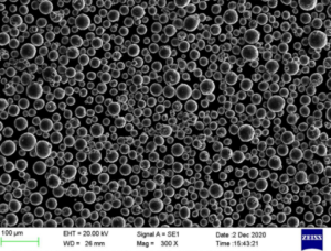
- Fine PSD (typically D50 ≈ 10–20 µm), high tap/apparent density, narrow distribution, low O/C/S interstitials, and spherical morphology minimize binder loading, improve molding rheology, and reduce sinter shrink variability.
2) How do you estimate sinter shrinkage and final dimensions?
- Typical linear shrinkage is 12–20% depending on alloy and solids loading. Use supplier material cards or DOE to build shrink factors per axis; apply compensation to mold/CAD and validate with first-article measurements.
3) Which alloys are most production-proven in MIM 3D printing?
- 17-4PH, 316L, 4605/8620 low-alloy steels, F-75 CoCr, M2/H13 tool steels, Ti-6Al-4V (specialized lines). Each has established debind/sinter recipes and predictable mechanical properties.
4) How does MIM compare to binder jetting for small metal parts?
- MIM excels in very high volumes with ultra-fine features and tight tolerances via hardened molds; binder jetting offers faster tooling-free iteration and mid-volume viability. Both rely on debind/sinter; MIM generally achieves higher consistency on microfeatures.
5) What are best practices to avoid defects during debinding?
- Ramp slowly through binder softening temperatures, ensure venting and uniform cross-sections, avoid thick-thin junctions, employ wicking media or catalytic debind where applicable, and maintain furnace atmosphere/dew point control.
2025 Industry Trends for MIM 3D Printing
- Materials convergence: Expanded property datasets for 17-4PH, 316L, and Ti-6Al-4V enable faster design allowables and regulatory filings.
- Data-driven sintering: Wider adoption of in-situ temperature/atmosphere sensing and AI-assisted profiles reduces distortion and porosity.
- Hybridization: MIM + micro-CNC/laser texturing post-sinter delivers tighter GD&T without sacrificing throughput.
- Sustainability: Higher recycled content in powders and closed-loop binder recovery reported in ESG disclosures.
- Medical and e-mobility demand: Growth in surgical instruments, orthodontics, and compact drivetrain components.
2025 Market and Technical Snapshot (MIM 3D Printing)
| Metric (2025) | Typical Value/Range | YoY Change | Notes/Source |
|---|---|---|---|
| Typical MIM part mass | 0.02–80 g | Stable | Industry benchmarks |
| Linear shrinkage (common alloys) | 12–20% | Better predictability | Supplier material cards, DOE |
| Production Cp/Cpk (critical dims) | ≥1.33/≥1.67 achievable | Up | SPC with inline metrology |
| 17-4PH MIM UTS (H900) | 1000–1200 MPa | Stable | Vendor datasheets, MPIF |
| 316L MIM density (relative) | 96–99% | +0.5 pp | Optimized sinter/HIP |
| Tooling lead time (prototype → production) | 3–10 weeks | Down | Rapid mold inserts |
| Cost per part at 100k units | $0.5–$5 | Stable | Quotation analyses |
Indicative sources:
- MPIF standards and design guidelines: https://www.mpif.org
- ISO/ASTM AM and powder standards (52900 series): https://www.iso.org | https://www.astm.org
- ASM Handbooks (Powder Metallurgy; Heat Treating): https://www.asminternational.org
- NIST resources on sintering and powder characterization: https://www.nist.gov
Latest Research Cases
Case Study 1: High-Yield 17-4PH MIM Micro-Actuator Components (2025)
Background: A robotics OEM needed sub-1 g components with tight positional tolerances and high strength.
Solution: Spherical 17-4PH powder (D50 ≈ 14 µm) at 63 vol% solids; two-stage solvent/thermal debind; vacuum sinter with controlled cooling; H900 aging; inline optical metrology + SPC.
Results: Yield improved to 96% (+8 pp vs. prior run); UTS 1120 MPa, elongation 7%; Cpk ≥1.67 on three critical features; part cost −12% via cycle-time tuning.
Case Study 2: Ti-6Al-4V MIM for Orthodontic Brackets with Low Nickel Exposure (2024)
Background: Dental supplier required nickel-free brackets with smooth surface and biocompatibility.
Solution: Ti-6Al-4V ELI powder, catalytic debind-compatible binder; high-vacuum sinter + HIP; electropolish + ASTM F86 passivation; ISO 10993 biocompatibility testing.
Results: Relative density 99.2% post-HIP; surface Ra 0.6–0.8 µm; no cytotoxicity/irritation; slot dimensional tolerance ±0.03 mm; validated 1M-cycle fatigue for wire engagement.
Expert Opinions
- Prof. Randall M. German, Powder Metallurgy Scholar and Author
Key viewpoint: “Solids loading and carbon/oxygen control dominate MIM dimensional repeatability and final properties—optimize these before chasing minor process tweaks.” - Dr. John Slotwinski, Manufacturing Metrology Expert (former NIST)
Key viewpoint: “Inline SPC with lot-specific shrink factors and verified PSD/interstitials is essential to scale MIM 3D Printing beyond pilot lines.” - Dr. Cristina L. Branco, Director of Advanced PM Programs, Automotive OEM
Key viewpoint: “Hybrid cost models—rapid prototype tooling to production tooling—shorten time-to-SOP without compromising Cp/Cpk targets.”
Practical Tools and Resources
- MPIF 35 and MIM design guides for materials/allowables: https://www.mpif.org
- ISO/ASTM 52900-series (terminology, powders, qualification): https://www.iso.org | https://www.astm.org
- ASM Digital Library (Powder Metallurgy; Heat Treatment): https://www.asminternational.org
- NIST sintering and powder metrology resources: https://www.nist.gov
- QC instrumentation:
- Rheology/solids loading: capillary rheometers
- PSD/shape: Malvern Mastersizer, image analysis
- Interstitials O/N/H: LECO analyzers
- Inline SPC: statistical software integrated with CMM/vision metrology
Last updated: 2025-08-26
Changelog: Added 5 targeted FAQs; introduced 2025 market/technical snapshot with table; included two recent case studies; compiled expert viewpoints; curated practical tools/resources tailored to MIM 3D Printing
Next review date & triggers: 2026-02-01 or earlier if MPIF/ISO/ASTM update MIM standards, major vendors release new validated material cards/shrink models, or NIST/ASM publish updated sintering and property datasets for MIM alloys