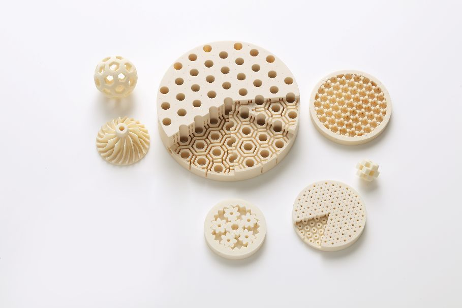
3D printing is also known as additive manufacturing, and additive manufacturing is a concept proposed as opposed to traditional subtractive manufacturing. We know that subtractive manufacturing is the process of cutting and sintering raw materials to produce parts, powder metallurgy, and cutting processes are all part of subtractive manufacturing. So, what does the corresponding additive manufacturing technology mean? And what technologies are used in additive manufacturing? This article will discuss what technology is used in 3D printing?
The Principle of 3D Printing
Before answering the question of what technology is used in 3D printing, it is necessary to understand the principles of 3D printing. 3D printing is a technology that uses digital model files as a basis for constructing objects by printing layer by layer using bondable materials such as powdered metal or plastic.
3D printing is usually achieved using digital technology material printers. It is often used to make models in mold-making and industrial design, and then gradually for the direct manufacture of some products, and parts have been printed using this technology.
Compared to traditional printing technologies and manufacturing processes, 3D printing has several features. Firstly, printing is done in a single pass, eliminating the need for repeated cutting and grinding, simplifying the process of product production, and shortening production
This simplifies the production process and shortens the production cycle. Secondly, the lower cost, especially in terms of batch production, is a significant cost advantage compared to traditional manufacturing. Finally, a higher degree of product sophistication.

3D Printing Technologies
FDM
Fused deposition modeling, (FDM), is a method of heating and melting various hot molten filamentary materials (wax, ABS and nylon, etc.) into shape and is a type of 3D printing technology. The FDM process utilizes the hot melt, bonding properties of thermoplastic materials stacked layer by layer under PLC control. Common base materials include thermoplastic materials, eutectic system metals, edible materials, etc.
EBF
Electron beam free-forming (EBF) is a process that uses an electron beam as a heat source to construct parts using off-axis metal wires. Near-net-formed parts made by this additive manufacturing process require subsequent finishing using a reduction process.
EBF technology can directly form metals such as aluminum, nickel, titanium, or stainless steel, and it is possible to mix two materials or to embed one into the other. The technology is suitable for almost any alloyed metal material.
DMLS
Direct metal laser sintering is a process used to mass-produce molds for injection molded parts and to manufacture metal products, but it can also be used in technologies such as extrusion or blow molding and other plastic processing. DMLS is suitable for 3D printing of almost any alloy.
Electron Beam Melting (EBM) is an emerging advanced metal additive manufacturing technology in recent years. The principle is to import the 3D solid model data of the part into the EBM equipment, then lay a thin layer of fine metal powder flat in the working chamber of the EBM equipment. The high density of energy generated at the focal point by the deflection and focus of the high energy electron beam causes the metal powder layer to be scanned to produce high temperatures in tiny localized areas, resulting in the melting of the metal particles, and the continuous scanning of the electron beam will cause the tiny pools of metal to fuse and solidify, connecting to form linear and faceted metal layers.
Selective laser melting is one of the main technologies used in the additive manufacturing of metal materials. It uses a laser as the energy source and scans the metal powder bed layer by layer according to the path planning in the 3D CAD cut-out model. The scanned metal powder is melted and solidified to achieve a metallurgical bonding effect, resulting in the metal part designed by the model. Mainly suitable for 3D printing on titanium, cobalt-chromium, stainless steel, aluminum, etc.
SLS
The SLS process, also known as selective laser sintering, was developed in 1989 by C.R. Dechard at the University of Texas at Austin, U.S.A. The SLS process uses powdered material for forming. The powdered material is spread on the upper surface of the formed part and scraped flat; a high-intensity CO2 laser is used to scan the part cross-section over the freshly laid new layer; the powdered material is sintered together under the high-intensity laser light to obtain a cross-section of the part, which is bonded to the formed part below; when one layer of the cross-section has been sintered, a new layer of material powder is laid on and the next layer of the cross-section is selectively sintered.
Above we have described some of the technologies used in 3D printing. In recent years, 3D printing technology has shown strong application advantages in many fields, and many precision parts and products based on 3D printing technology have had a positive impact in promoting industrial development and innovation.
With the development of complementary technologies, more printing materials will be available in the future, and 3D printing will reduce the cost of printing equipment and enhance the human and intelligent nature of printing operations, thus providing technical support for social and economic development.
This will provide technical support for social and economic development.
Contact Turer to get a free metal 3D printing Solution!
Frequently Asked Questions (Supplemental)
1) Which 3D printing technology should I choose for functional metal parts?
- Selective Laser Melting (SLM)/Direct Metal Laser Sintering (DMLS) or Electron Beam Melting (EBM) are best for end-use metal parts. SLM/DMLS offers finer features and smoother surfaces; EBM provides faster builds and lower residual stress for Ti alloys.
2) How do SLS and SLM differ in practice?
- SLS typically sinters polymers (PA12, TPU) or metal/polymer composites; SLM fully melts metal powders to near‑wrought density. SLS excels in durable polymer prototypes; SLM suits structural metal components.
3) What are typical build sizes and layer thicknesses across 3D printing?
- FDM: 100–400 μm layers; desktop to 300×300×400 mm. SLS: 80–150 μm; 300×300×400 mm common. SLM/DMLS: 20–60 μm; 250×250×300 mm up to >400 mm cubes. EBM: 50–100 μm; similar or larger build volumes.
4) How do material properties compare between AM and wrought?
- With optimized parameters and post‑processing (HIP/heat treatment), SLM/DMLS and EBM can reach ≥99.8% density and tensile properties close to or exceeding wrought in certain alloys (e.g., Ti‑6Al‑4V, 17‑4PH). Anisotropy and surface roughness must be managed.
5) What standards govern validation of 3D printed parts?
- ISO/ASTM 52900 series for terminology; 52904 (metal PBF); 52921 (design); ASTM F3122 (property reporting), F3301/F3303 (process control). Medical/aerospace add ISO 13485 or AS9100 quality systems.
2025 Industry Trends and Data
- Multi‑laser coordination: Advanced scan strategies reduce stitch defects and boost throughput in metal PBF.
- High‑throughput polymers: SLS with faster IR sources and automated powder handling lowers part cost.
- Copper and aluminum in PBF: Green/blue lasers improve conductivity parts yield for EV and thermal management.
- Software‑first workflows: Build simulation and in‑situ monitoring shorten qualification cycles.
- ESG reporting: Powder passports with recycled content and O/N/H data increasingly required in RFQs.
| KPI (3D Printing, 2025) | 2023 Baseline | 2025 Typical/Target | Tech area | Why it matters | Sources/Notes |
|---|---|---|---|---|---|
| Metal PBF layer thickness (μm) | 30–60 | 20–50 | SLM/DMLS | Feature resolution, density | ISO/ASTM 52904; OEM specs |
| As‑built density after HIP (%) | 99.5–99.8 | 99.8–99.95 | Metal PBF | Fatigue/leak‑tightness | OEM/peer‑reviewed data |
| Polymer SLS refresh ratio (new:used) | 30:70 | 20:80 | SLS | Cost, consistency | Vendor apps guides |
| Multi‑laser productivity gain | 20–40% | 35–60% | Metal PBF | Cost per part | Machine vendors |
| Build failure rate with in‑situ monitoring | 8–12% | 3–6% | PBF/EBM | Yield | NIST AM Bench; case studies |
| Copper PBF conductivity vs. wrought | 80–90% IACS | 90–95% IACS | Green/blue laser PBF | Electrical performance | OEM test data |
Authoritative resources:
- ISO/ASTM 52900 family: https://www.iso.org
- ASTM F3122, F3301, F3303: https://www.astm.org
- NIST AM Bench datasets: https://www.nist.gov/ambench
- SAE AMS7000 series (AM metals): https://www.sae.org
- FDA AM guidance (medical devices): https://www.fda.gov
Latest Research Cases
Case Study 1: Blue‑Laser PBF for High‑Conductivity Copper Busbars (2025)
- Background: An EV supplier needed dense Cu components with >90% IACS conductivity for compact power modules.
- Solution: Blue‑laser PBF with high‑sphericity Cu powder (D50 ≈ 30 μm), optimized hatch and contour, in‑situ melt‑pool monitoring; stress relief and surface tumbling.
- Results: Density 99.7% as‑built; conductivity 92–94% IACS; scrap rate reduced from 11% to 4%; assembly footprint −18% due to integrated cooling features.
Case Study 2: Hybrid EBM + CNC for Ti‑6Al‑4V Orthopedic Implants (2024)
- Background: A medical OEM sought porous‑core stems with consistent osseointegration and tight taper fits.
- Solution: EBM lattices (pore 500–800 μm) fused to solid features; HIP + aging; precision CNC on taper surfaces; validated per ISO 10993 and ASTM F3001.
- Results: Shear strength across lattice/solid interface +22% vs. prior design; pore interconnectivity >95%; CT porosity <0.1%; regulatory submission time reduced by 3 months due to standardized datasets.
Expert Opinions
- Dr. Brent Stucker, Senior Director of Additive Manufacturing, Ansys
- Viewpoint: “Predictive simulation of distortion and melt‑pool behavior is now table stakes—closing the loop with in‑situ sensing cuts trial‑and‑error and qualifies builds faster.”
- Prof. Iain Todd, Professor of Metallurgy, University of Sheffield
- Viewpoint: “Alloy design tailored for PBF—especially for Al and Cu—removes fundamental printability barriers without sacrificing properties.”
- Dr. Laura Ely, Managing Director, AM Research Consortium (AMRC)
- Viewpoint: “Standardized test artifacts and powder passports are accelerating cross‑platform comparability and supplier qualification.”
Affiliation links:
- Ansys Additive: https://www.ansys.com
- University of Sheffield (Materials): https://www.sheffield.ac.uk
- AMRC: https://www.amrc.co.uk
Practical Tools/Resources
- Design/simulation: Ansys Additive; Autodesk Netfabb; Simufact Additive; nTopology for lattices
- Standards: ISO/ASTM 52900, 52904, 52910; SAE AMS7000 series
- Databases: Senvol Database (https://senvol.com/database) for machine/material/process data
- Metrology: CT scanning best practices (NPL, NIST); surface roughness and porosity guides
- QA/Monitoring: Sigma Additive Quality, EOS EOSTATE, Renishaw InfiniAM; powder passport templates
- Safety: NFPA 484 (combustible metals), ISO 80079 (explosive atmospheres), supplier SDS
Last updated: 2025-08-22
Changelog: Added 5 supplemental FAQs; included 2025 KPI table and trends; added two recent case studies (blue‑laser copper PBF; hybrid EBM+CNC implants); provided expert viewpoints with affiliations; compiled practical tools/resources for 3D Printing selection and validation.
Next review date & triggers: 2026-02-01 or earlier if ISO/ASTM standards update, major OEMs release new alloy/process parameters, or new datasets on in‑situ monitoring and multi‑laser coordination are published.

