Overview
slm, which stands for selective laser melting, is an additive manufacturing process that uses a laser to selectively melt and fuse metallic powder material layer by layer to build a 3D part. It is one of the most commonly used metal 3D printing technologies today.
Some key things to know about slm equipment:
- Works with various metals including stainless steels, titanium, aluminum, nickel alloys, and more
- Uses a high power laser to selectively melt metal powder particles in a powder bed
- Builds parts layer-by-layer by spreading thin layers of powder and scanning the laser to melt the cross-section
- Produces fully dense metal parts with mechanical properties comparable to traditional manufacturing
- Enables complex geometries not possible with conventional subtractive methods
- Well-suited for small batch production, customized parts, and rapid prototyping
- slm machines consist of a laser, scanner system, powder bed, recoater mechanism and more
This guide provides a comprehensive overview of slm equipment covering the working, types, applications, specifications, suppliers, installation, operation, maintenance, and more. Let’s explore the world of selective laser melting equipment!
slm Equipment Types
There are several categories and types of slm equipment available from various manufacturers. Here is a comparison:
| Equipment Type | Build Size | Laser Type | Key Characteristics |
|---|---|---|---|
| Desktop slm | 50-150 mm | Fiber, CO2 | Compact size, lower cost, R&D, small parts |
| Benchtop slm | 150-300 mm | Fiber, CO2 | Larger build volume, moderate cost |
| Industrial slm | 300-500 mm | Fiber, CO2 | High capacity, automated production |
| Large-format slm | 500+ mm | Fiber | For large parts, high productivity |
The main factors that differentiate slm machine types include:
- Build volume – Maximum part size that can be printed. Ranges from a few cm for desktop to >1 m for large systems.
- Laser type – Fiber lasers allow faster processing. CO2 lasers are lower cost.
- Automation – Industrial systems have higher levels of automation and control.
- Inert gas use – Larger machines more often use inert argon gas vs. smaller using air.
- Price – Desktop and benchtop models are lower cost with reduced capacity.
So in summary, desktop and benchtop slm equipment is well-suited for prototyping and R&D purposes while industrial and large-format systems are designed for volume production applications. Consider build size, price, quality needs and other requirements when selecting an slm machine type.

slm Equipment Components
slm machines consist of several main sub-systems and components that work together to enable the additive manufacturing process. Here are the key components:
| Component | Description |
|---|---|
| Laser | Provides focused heat energy to selectively melt the powder material |
| Scanning system | Controls and positions the laser beam precisely |
| Powder bed | Holds and spreads the metal powder layers |
| Recoater | Spreads and levels fresh powder over the build area |
| Powder delivery | Feeds new powder from cartridge/container |
| Build plate | Holds the printed part as layers accumulate |
| Inert gas flow | Protective atmosphere of argon or nitrogen gas |
| Computer | Controls hardware, executes build file |
| Chiller | Cools laser and sensitive optics |
| Filters | Capture excess powder and particles |
The laser is one of the most critical components. slm machines typically use either a fiber laser (ytterbium-doped) or CO2 laser with power levels from 100 to 1000 watts. The laser scanning system directs the laser beam across the powder bed surface and scans the cross-section of each layer.
Other key hardware includes the powder bed which holds the raw material powder, recoater to spread new layers of powder, inert gas flow system, various sensors, and more. The integrated control software converts CAD data into instructions for the equipment to follow layer-by-layer.
slm Equipment Specifications
slm machines can be compared by various technical specifications and performance parameters. Here are some key specifications to consider for slm systems:
| Specification | Typical Range |
|---|---|
| Build volume | 50mm – 500mm edge length |
| Layer thickness | 20-100 microns |
| Laser power | 100-1000W |
| Scanning speed | Up to 10 m/s |
| Beam size | 50-100 microns |
| Powder material | Stainless steel, titanium, Ni alloys, Al alloys, more |
| Supported materials | Most weldable alloys |
| Precision | ± 0.1-0.2% dimensional accuracy |
| Surface finish | Up to 15 microns roughness |
Other factors like the inert gas consumable usage, filtering system effectiveness, software capabilities, and more also differentiate slm equipment models and performance. In general, industrial systems offer larger build volumes, higher laser power, faster scanning speeds, and better process control compared to desktop models.
slm Equipment Design Considerations
slm machines involve precision design and engineering across optical, mechanical, electronic, and software systems. Some key design factors include:
- Laser optics – Well-configured galvo/mirror system for accurate laser steering and spot sizing.
- Powder handling – Minimizing jamming and ensure smooth powder flow.
- Gas flow – Managing laminar flow across powder bed.
- Build plate – Withstanding repeated high temperatures.
- Controls – Precisely monitoring and adjusting parameters in real-time.
- Filters – Capturing micron-scale metallic particles and powder.
- Contamination prevention – Keeping sensitive optics clean.
- Calibration – Maintaining alignment and calibration during operation.
- Automation-readiness – Allowing integration of material handling systems.
Careful slm equipment design is needed to achieve repeatable, high-quality builds in a production environment. Leading manufacturers continue to refine the hardware and software for better process control.
slm Equipment Suppliers
There is a range of companies that manufacture and provide slm equipment solutions. Here are some of the major suppliers:
| Supplier | Equipment Brands/Models |
|---|---|
| EOS | EOS M series, EOS P series |
| SLM Solutions | SLM®125, SLM®280, SLM®500, SLM®800 |
| GE Additive | Concept Laser M2, MLine, XLine 500R |
| 3D Systems | ProX® DMP 100, 200, 300, 320 |
| Trumpf | TruPrint 1000, 3000, 5000 |
| Renishaw | RenAM 500Q, RenAM 500M |
| Sisma | Sisma Mysint100, Mysint300 |
In addition, there are a growing number of suppliers from Asia that offer more affordable desktop slm equipment including:
- Farsoon
- Longer 3D
- Raycham
- Wiiboox
- Creality
When selecting an slm equipment supplier, key considerations include build quality, reliability, service, customer support, powder handling features, software capabilities, pricing, and prior user experiences. Leading original equipment manufacturers tend to offer proven technology and performance.

slm Equipment Pricing
The cost of slm equipment can range quite widely depending on the build volume, features, and manufacturer. Here is an overview of typical pricing ranges:
| slm Equipment Type | Approximate Cost Range |
|---|---|
| Desktop slm | $50,000 – $150,000 |
| Benchtop slm | $150,000 – $300,000 |
| Industrial slm | $300,000 – $1,000,000 |
| Large-format slm | $1,000,000+ |
In general, industrial slm systems from original equipment manufacturers cost between $300,000 to $1,000,000. Larger build envelopes, higher powered lasers, and greater automation increase the price.
Affordable desktop models from Asian suppliers are available under $100,000. Many offer similar capabilities to higher priced equipment but may lack in reliability, performance, or service.
Total costs also include ongoing operating costs for metal powders, filters, gas supplies, maintenance, repairs, and spare parts which can be substantial. Both equipment purchase costs and operating costs should be considered.
slm Equipment Installation
Proper installation of slm equipment helps ensure safe and optimal operation. Here are key installation steps:
- Unpack machine components carefully and check for damage.
- Position on sturdy frame or table to minimize vibration.
- Level build platform precisely.
- Connect chiller, gas supplies, ventilation ducting.
- Install fume extraction unit/filter.
- Connect electrical power supply.
- Install and calibrate all optics and laser path.
- Test motion of recoater, powder system.
- Integrate monitoring sensors.
- Establish closed-loop powder handling system.
- Initialize and calibrate machine settings.
- Perform sample test builds and validate quality.
Adequate facility preparation is also required including space, power supply, stable temperature/humidity, ventilation, hazardous material handling capabilities, and more. Installation is typically completed by the equipment manufacturer representatives.
slm Equipment Operation
Operating an slm machine requires careful supervision, system monitoring, standard protocols, and build validation. Here are key operating procedures:
- Import and prepare 3D CAD model into slicer software.
- Select process parameters and generate build files.
- Sieve and load metal powder into system.
- Select and mount build plate.
- Adjust layer thickness, laser power, speed, etc.
- Initiate inert gas flow and preheat powder bed.
- Initiate first layer powder spreading and laser scanning.
- Periodically monitor temperature, powder levels, gas flow.
- Allow layers to complete until full build height is reached.
- Remove build plate when finished and recover part.
- Remove excess powder using blasting techniques.
- Post-process part as needed – annealing, machining, etc.
Critical process parameters that are controlled include laser power, scanning pattern, scanning speed, hatch spacing, layer thickness, preheat temperature and others. Real-time monitoring and adjustment is often required.
Safety equipment for respiratory and eye protection along with hazardous power training is mandatory. Parts also undergo validation testing to verify required material properties.
slm Equipment Maintenance
Routine preventative maintenance helps maximize uptime and performance. Maintenance tasks include:
- Cleaning – Keep optics, laser path and sensors clear of dirt and debris.
- Calibration – Realign and calibrate sensors, lasers, optics.
- Filter change – Replace air and powder filters regularly.
- Recoater – Lubricate/replace recoater blades, adjust gap.
- Laser – Monitor beam quality and adjust resonator alignment.
- Motion – Lubricate linear stages, replace worn components.
- Powder – Dispose excess powder regularly to avoid clumping/caking.
- Safety checks – Confirm status of gas detectors, alarms, sensors.
- Firmware – Install software and firmware updates from vendor.
Manufacturers provide maintenance manuals detailing schedules for daily, weekly, monthly recommended maintenance. Consumable parts like filters and recoater blades require routine change outs. Maintenance contracts can provide regular preventative service.
Applications of slm Equipment
slm technology is well-suited for various applications across different industries. Here are some typical applications:
Aerospace – Turbine blades, structural brackets, rocket nozzles
Medical – Orthopedic implants, prosthetics, surgical instruments
Automotive – Lightweighting parts, custom tooling
Industrial – Heat exchangers, fluid handling parts
Defense – Components for firearms, armor
Jewelry – Customized precious metal jewelry
Key advantages of slm for these applications include consolidating assemblies into one part, weight reduction, complex cooling channels, freeform shapes, rapid turnaround, and more.
The high precision, small feature size, and excellent mechanical properties of slm make it ideal for fabricating lightweight, optimized and custom components across sectors.
How to Select an slm Equipment Supplier
Selecting the right slm equipment and supplier is an important decision. Here are key considerations when choosing an slm supplier:
- Build quality – Evaluate sample parts to ensure good density, properties, accuracy.
- Reliability – Seek field data on meantime between failures and longevity.
- Technical support – Assess response time and support infrastructure.
- Warranty – Review warranty terms on hardware, optics, etc.
- Training – Check availability of operation and maintenance training.
- Materials range – Consider available powder materials and quality.
- Software – Examine built-in software capabilities and ease of use.
- Regional presence – Determine availability of local application engineers.
- Service contracts – Compare post-sale maintenance contracts and SLAs.
- Pricing – Balance purchase cost, TCO and performance value.
Narrow down the shortlist based on build specifications, price range, and risk tolerance. Schedule equipment demos and evaluate sample part quality firsthand from potential suppliers before final purchase decision.
slm vs Other Metal 3D Printing Processes
slm is one of several metal additive manufacturing technologies each with their own profiles. Here is how slm compares:
| Process | Pros | Cons |
|---|---|---|
| Selective Laser Melting (slm) | Excellent properties, high precision, most alloys | Lower speed, higher cost, residual stresses |
| Direct Metal Laser Sintering (DMLS) | Good material properties, low costs | Porosity issues in some alloys |
| Electron Beam Melting (EBM) | Excellent structural properties, near full density | Less alloys supported, moderate precision |
| Directed Energy Deposition (DED) | Large parts, metal deposition, repairs | Lower resolution, higher cost |
Key Differences:
- slm produces fully dense, void-free structures in a wider range of alloys but at lower build speeds.
- DMLS powder is sintered vs. fully melted, limiting material performance.
- EBM requires a vacuum, supports fewer alloys but delivers excellent material properties.
- DED has lower precision but supports large metal deposition applications.
For most high-value production components, slm provides superior material properties. But for large repairs or simpler shapes, DED or DMLS can be more cost-effective.

Advantages and Limitations of slm
Like any technology, slm has both advantages and limitations to consider:
Advantages
- High dimensional accuracy and fine surface finish
- Excellent mechanical properties maintained throughout builds
- Complex geometries and lightweight structures possible
- Consolidated parts and assemblies
- Rapid turnaround for design iterations
- Customized shapes, features, and designs
Limitations
- Small build envelopes restrict part sizes
- Relatively slow production rates
- Supports limited materials – mostly metals
- Significant post-processing often required
- Residual stresses can cause deformation
- High equipment and material costs
Understand application requirements and compare process tradeoffs to determine if slm is the most suitable AM process. slm provides a versatile tool for metal part production but requires experience to optimize applications.
FAQ
Here are answers to some frequently asked questions about slm equipment:
Q: What metals can be processed using slm?
A: Most weldable alloys including stainless steel, titanium, nickel alloys, aluminum, tool steel, and more. New materials are continually validated.
Q: What are typical layer resolutions for slm machines?
A: Layer thicknesses range from 20 to 100 microns, with 50 microns being common. Finer layers improve surface finish but also increase build time.
Q: How large of a part can be made with slm?
A: Desktop systems support builds up to 100-150mm size while industrial slm machines allow 500mm build envelopes or larger.
Q: What processes are required after slm printing?
A: Post-processing steps include support removal, media blasting, annealing, machining, polishing, and applying surface treatments.
Q: What types of accuracy and surface finishes are achieved?
A: Dimensional accuracy reaches ±0.1-0.2% with surface finishes around 15 microns roughness, depending on parameters.
Q: What safety precautions are required for operation?
A: Proper PPE including respirators, protective eyewear, gloves, and hazardous material handling training. Proper ventilation and safe powder handling are critical.
Q: What maintenance is required for slm machines?
A: Regular maintenance includes optics/laser cleaning, filter changes, powder disposal, lubrication, calibrations, firmware upgrades, and more.
Q: How long does it take to set up a build job on an slm machine?
A: With prepared CAD models, orienting parts, setting parameters and slice times, starting a build can range from 30 minutes to a few hours.
Conclusion
slm provides transformative capabilities for dense, high-performance metal part production. Understanding the different equipment types, working principles, specifications, applications, and advantages allows the technology to be leveraged effectively. With continual advances in machines, materials, software, and process control, slm promises to become even more competitive against conventional manufacturing.
know more 3D printing processes
Additional FAQs on slm Equipment
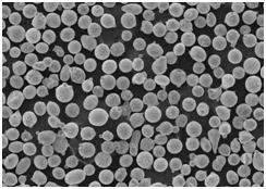
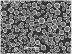
1) What powder specifications are critical for stable slm builds?
Spherical morphology, PSD D10–D90 ≈ 15–45 μm (material dependent), low interstitials (O/N/H), high flowability (Hall/Carney), consistent apparent/tap density, and minimal satellites per ISO/ASTM 52907.
2) How do multi-laser slm systems coordinate scan fields without defects?
They use advanced tiling/overlap strategies, laser synchronization, and shared calibration to prevent stitch lines and ensure uniform energy density across the full build.
3) What are effective strategies to reduce residual stress and distortion?
Use platform preheat (e.g., 80–200°C), thin layers, optimized hatch rotations, contour-first strategies, robust support design, and post-build stress relief or HIP when required.
4) How should powder reuse be managed on slm equipment?
Adopt closed-loop sieving, track powder genealogy, apply blend-back limits (e.g., 20–50% recycled), and test O/N/H, PSD, and flow routinely; retire powder when out of spec.
5) Which alloys are challenging on slm and why?
High-reflectivity Cu/Al grades and crack‑prone Ni superalloys can suffer lack‑of‑fusion or fissuring; wavelength-optimized lasers, tailored scan strategies, and preheat mitigate risks.
2025 Industry Trends for slm
- Multi-laser normalization: 8–12 laser machines with smarter tiling deliver 20–40% faster cycle times.
- In‑situ acceptance: Melt‑pool/coaxial cameras tied to part acceptance reduce CT burden for well‑characterized geometries.
- Copper- and aluminum‑ready platforms: Blue/green lasers expand material portfolio beyond traditional steels/Ti/Ni.
- Sustainability and safety: Argon recirculation, closed powder loops, and NFPA 484‑aligned rooms become standard in production.
- MES integration: Material passports linking powder lots to serial numbers for traceability and qualification.
| 2025 Metric (slm Equipment/Process) | Typical Range/Value | Why it matters | Source |
|---|---|---|---|
| LPBF relative density (post‑HIP, common alloys) | 99.5–99.9% | Production-grade integrity | Peer-reviewed AM studies; OEM notes |
| Build rate (12‑laser, 40 μm layers) | 35–70 cm³/h per system | Lowers cost per part | OEM application notes |
| Typical PSD for slm powders | D10–D90 ≈ 15–45 μm | Recoating stability | ISO/ASTM 52907 |
| Oxygen spec (Ti‑6Al‑4V ELI) | ≤0.13 wt% O | Ductility/biocompatibility | ASTM F136/F3001 |
| Indicative machine uptime (with PM) | 75–90% | Planning and ROI | Industry benchmarks |
| AM‑grade powder pricing range | ~$20–$500/kg | Budgeting and sourcing | Supplier quotes/trackers |
Authoritative references and further reading:
- ISO/ASTM 52907 (AM feedstock), 52910 (DFAM), 52931 (LB‑PBF metals): https://www.astm.org and https://www.iso.org
- NFPA 484 (combustible metals safety): https://www.nfpa.org
- NIST AM Bench and datasets: https://www.nist.gov
- ASM Handbook (Powder Metallurgy; Materials Systems): https://www.asminternational.org
Latest Research Cases
Case Study 1: Scaling Multi‑Laser slm for Stainless Lattice Heat Exchangers (2025)
Background: An industrial OEM needed to cut cycle time on 316L lattice heat exchangers while maintaining pressure integrity.
Solution: Deployed a 12‑laser slm system with coordinated tiling, in‑situ melt‑pool monitoring, and automated powder genealogy; post‑HIP and passivation.
Results: 29% cycle time reduction; >99.8% density post‑HIP; 30% reduction in CT usage on validated sections; 15% lower pressure drop at constant duty.
Case Study 2: slm of Cu‑Cr‑Zr Thermal Plates Using Blue Lasers (2024)
Background: An e‑mobility supplier required high‑conductivity cold plates with tight flatness after thermal cycling.
Solution: Spherical Cu‑Cr‑Zr powder (15–45 μm) printed on blue‑laser slm with platform preheat, optimized contour/hatch; HIP + aging; Ni flash on sealing lands.
Results: Conductivity 80–85% IACS; flatness within 30 μm after 1,000 cycles (−40 to 150°C); 18% cost reduction vs. machined baseline.
Expert Opinions
- Prof. John Hart, Professor of Mechanical Engineering, MIT
Key viewpoint: “Linking in‑situ sensing with material passports is enabling defensible acceptance criteria for serial slm production.” - Dr. Laura Schmidt, Head of Additive Manufacturing, Fraunhofer IAPT
Key viewpoint: “Multi‑laser coordination and wavelength‑optimized optics are expanding slm into copper and high‑productivity applications without compromising quality.” - Dr. Brent Stucker, AM standards contributor and industry executive
Key viewpoint: “Hybrid flows—slm preforms plus HIP/forging—achieve wrought‑like properties where needed while keeping AM design freedom.”
Citations for expert profiles:
- MIT: https://meche.mit.edu
- Fraunhofer IAPT: https://www.iapt.fraunhofer.de
- ASTM AM Center of Excellence: https://amcoe.org
Practical Tools and Resources
- Standards and qualification
- ISO/ASTM 52907, 52910, 52931; ASTM E1441 (CT best practices); NFPA 484
- Powder QC and monitoring
- LECO O/N/H analyzers: https://www.leco.com
- Laser diffraction/SEM (e.g., Malvern, accredited labs)
- Inline O2/moisture sensors for chambers
- Design and simulation
- Ansys Additive/Mechanical; Simufact Additive; nTopology for supports/lattices
- Market and data
- Senvol Database (machines/materials): https://senvol.com/database
- USGS Mineral Commodity Summaries: https://pubs.usgs.gov/periodicals/mcs
- NIST AM Bench datasets: https://www.nist.gov
Last updated: 2025-08-21
Changelog: Added 5 focused FAQs, a 2025 trends table with metrics and sources, two recent slm case studies, expert viewpoints with citations, and curated tools/resources.
Next review date & triggers: 2026-02-01 or earlier if ISO/ASTM standards update, major OEMs release new multi‑laser coordination or blue‑laser slm platforms, or powder pricing/availability shifts >10% QoQ.