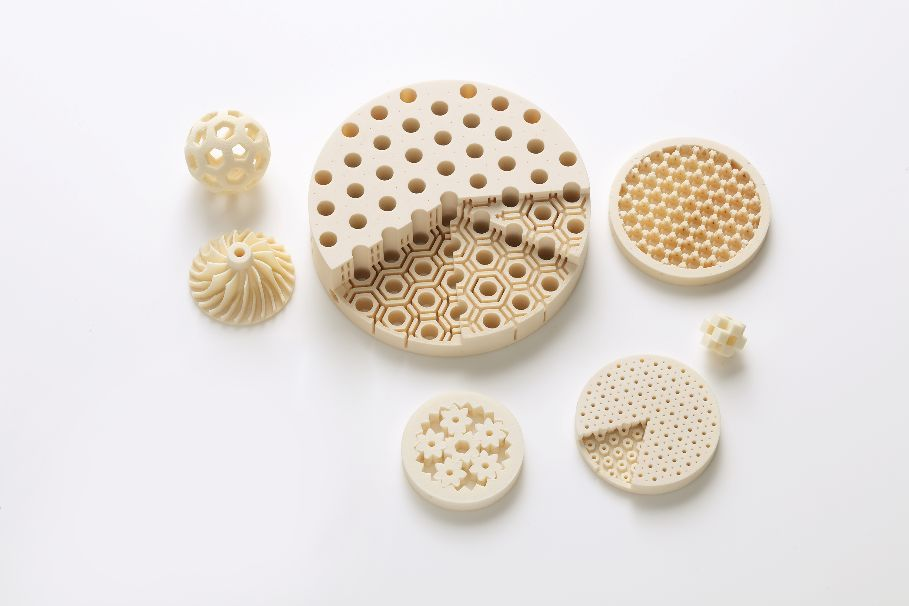
3D 프린팅은 적층 제조적층 제조는 기존의 감산 제조와 반대되는 개념으로 제안된 개념입니다. 감산 제조는 원료를 절단하고 소결하여 부품을 생산하는 공정으로, 분말 야금 및 절단 공정이 모두 감산 제조의 일부라는 것을 알고 있습니다. 그렇다면 해당 적층 제조 기술은 무엇을 의미할까요? 그리고 적층 제조에는 어떤 기술이 사용되나요? 이번 글에서는 3D 프린팅에는 어떤 기술이 사용되나요?
3D 프린팅의 원리
3D 프린팅에 어떤 기술이 사용되는지에 대한 질문에 답하기 전에 3D 프린팅의 원리를 이해할 필요가 있습니다. 3D 프린팅은 디지털 모델 파일을 기초로 하여 분말 금속이나 플라스틱과 같은 접착 가능한 재료를 사용하여 층층이 인쇄하여 물체를 만드는 기술입니다.
3D 프린팅은 일반적으로 디지털 기술 재료 프린터를 사용하여 이루어집니다. 금형 제작 및 산업 디자인에서 모델을 만드는 데 자주 사용되다가 점차 일부 제품의 직접 제조에 사용되며 이 기술을 사용하여 부품을 인쇄하고 있습니다.
기존 인쇄 기술 및 제조 공정과 비교했을 때 3D 인쇄는 몇 가지 특징이 있습니다. 첫째, 인쇄가 한 번에 이루어지므로 반복적인 절단과 연삭이 필요 없고 제품 생산 과정이 단순화되며 생산 시간이 단축됩니다.
이는 생산 프로세스를 단순화하고 생산 주기를 단축합니다. 둘째, 특히 일괄 생산 측면에서 비용이 절감되므로 기존 제조 방식에 비해 상당한 비용 이점이 있습니다. 마지막으로, 더 높은 수준의 제품 정교함입니다.

3D 프린팅 기술
FDM
용융 증착 모델링(FDM)은 왁스, ABS, 나일론 등 다양한 고온 용융 필라멘트 소재를 가열하여 녹여 모양을 만드는 방법으로 3D 프린팅 기술의 일종입니다. FDM 공정은 PLC 제어 하에 열가소성 소재를 층층이 쌓아 올리는 핫멜트, 결합 특성을 활용합니다. 일반적인 기본 재료로는 열가소성 재료, 공융 시스템 금속, 식용 재료 등이 있습니다.
EBF
전자 빔 자유 성형(EBF)은 전자 빔을 열원으로 사용하여 축을 벗어난 금속 와이어를 사용하여 부품을 제작하는 공정입니다. 이 적층 제조 공정으로 만든 그물망에 가까운 부품은 환원 공정을 사용하여 후속 마감이 필요합니다.
EBF 기술은 알루미늄, 니켈, 티타늄 또는 스테인리스 스틸과 같은 금속을 직접 성형할 수 있으며, 두 가지 재료를 혼합하거나 한 재료를 다른 재료에 삽입할 수 있습니다. 이 기술은 거의 모든 합금 금속 소재에 적합합니다.
DMLS
직접 금속 레이저 소결은 사출 성형 부품의 금형을 대량 생산하고 금속 제품을 제조하는 데 사용되는 공정이지만 압출 또는 블로우 성형 및 기타 플라스틱 가공과 같은 기술에도 사용할 수 있습니다. DMLS는 거의 모든 합금의 3D 프린팅에 적합합니다.
전자빔 용융(EBM)은 최근 떠오르는 첨단 금속 적층 제조 기술입니다. 원리는 부품의 3D 솔리드 모델 데이터를 EBM 장비로 가져온 다음 EBM 장비의 작업 챔버에 얇은 금속 분말 층을 평평하게 놓는 것입니다. 고에너지 전자빔의 편향과 초점에 의해 초점에서 생성되는 고밀도 에너지로 인해 금속 분말 층이 스캔되어 작은 국소 영역에서 고온이 발생하여 금속 입자가 용융되고 전자빔의 연속 스캔으로 인해 작은 금속 풀이 융합 및 응고되어 선형 및 패싯 금속 층을 형성하기 위해 연결됩니다.
선택적 레이저 용융은 금속 재료의 적층 제조에 사용되는 주요 기술 중 하나입니다. 레이저를 에너지원으로 사용하여 3D CAD 컷아웃 모델의 경로 계획에 따라 금속 분말 층을 한 층씩 스캔합니다. 스캔한 금속 분말을 녹이고 고형화하여 야금 결합 효과를 얻어 모델에서 설계한 금속 부품을 만듭니다. 주로 티타늄, 코발트-크롬, 스테인리스 스틸, 알루미늄 등의 3D 프린팅에 적합합니다.
SLS
선택적 레이저 소결이라고도 하는 SLS 공정은 1989년 미국 오스틴에 있는 텍사스 대학교의 C.R. Dechard가 개발한 것으로, 분말 재료를 성형에 사용합니다. 분말 재료를 성형 부품의 윗면에 펴서 평평하게 긁어내고, 고강도 CO2 레이저를 사용하여 새로 놓인 새 층 위에 부품 단면을 스캔하고, 고강도 레이저 빛 아래에서 분말 재료를 함께 소결하여 부품 단면을 얻고, 이 단면의 한 층이 소결되면 새로운 재료 분말 층을 얹고 다음 단면의 층을 선택적으로 소결하는 방식으로 이루어집니다.
위에서 3D 프린팅에 사용되는 몇 가지 기술에 대해 설명했습니다. 최근 몇 년 동안 3D 프린팅 기술은 여러 분야에서 강력한 응용 이점을 보여 왔으며 3D 프린팅 기술을 기반으로 한 많은 정밀 부품과 제품이 산업 발전과 혁신을 촉진하는 데 긍정적인 영향을 미쳤습니다.
보완 기술의 발전으로 앞으로 더 많은 인쇄 재료를 사용할 수 있게 될 것이며, 3D 프린팅은 인쇄 장비 비용을 절감하고 인쇄 작업의 인간적이고 지능적인 특성을 강화하여 사회 및 경제 발전을 위한 기술 지원을 제공할 것입니다.
이를 통해 사회 및 경제 발전을 위한 기술 지원을 제공할 것입니다.
Turer에 문의 를 클릭해 금속 3D 프린팅 솔루션을 무료로 받으세요!
Frequently Asked Questions (Supplemental)
1) Which 3D printing technology should I choose for functional metal parts?
- Selective Laser Melting (SLM)/Direct Metal Laser Sintering (DMLS) or Electron Beam Melting (EBM) are best for end-use metal parts. SLM/DMLS offers finer features and smoother surfaces; EBM provides faster builds and lower residual stress for Ti alloys.
2) How do SLS and SLM differ in practice?
- SLS typically sinters polymers (PA12, TPU) or metal/polymer composites; SLM fully melts metal powders to near‑wrought density. SLS excels in durable polymer prototypes; SLM suits structural metal components.
3) What are typical build sizes and layer thicknesses across 3D printing?
- FDM: 100–400 μm layers; desktop to 300×300×400 mm. SLS: 80–150 μm; 300×300×400 mm common. SLM/DMLS: 20–60 μm; 250×250×300 mm up to >400 mm cubes. EBM: 50–100 μm; similar or larger build volumes.
4) How do material properties compare between AM and wrought?
- With optimized parameters and post‑processing (HIP/heat treatment), SLM/DMLS and EBM can reach ≥99.8% density and tensile properties close to or exceeding wrought in certain alloys (e.g., Ti‑6Al‑4V, 17‑4PH). Anisotropy and surface roughness must be managed.
5) What standards govern validation of 3D printed parts?
- ISO/ASTM 52900 series for terminology; 52904 (metal PBF); 52921 (design); ASTM F3122 (property reporting), F3301/F3303 (process control). Medical/aerospace add ISO 13485 or AS9100 quality systems.
2025 Industry Trends and Data
- Multi‑laser coordination: Advanced scan strategies reduce stitch defects and boost throughput in metal PBF.
- High‑throughput polymers: SLS with faster IR sources and automated powder handling lowers part cost.
- Copper and aluminum in PBF: Green/blue lasers improve conductivity parts yield for EV and thermal management.
- Software‑first workflows: Build simulation and in‑situ monitoring shorten qualification cycles.
- ESG reporting: Powder passports with recycled content and O/N/H data increasingly required in RFQs.
| KPI (3D Printing, 2025) | 2023 Baseline | 2025 Typical/Target | Tech area | Why it matters | Sources/Notes |
|---|---|---|---|---|---|
| Metal PBF layer thickness (μm) | 30–60 | 20–50 | SLM/DMLS | Feature resolution, density | ISO/ASTM 52904; OEM specs |
| As‑built density after HIP (%) | 99.5–99.8 | 99.8–99.95 | Metal PBF | Fatigue/leak‑tightness | OEM/peer‑reviewed data |
| Polymer SLS refresh ratio (new:used) | 30:70 | 20:80 | SLS | Cost, consistency | Vendor apps guides |
| Multi‑laser productivity gain | 20–40% | 35–60% | Metal PBF | 부품당 비용 | Machine vendors |
| Build failure rate with in‑situ monitoring | 8–12% | 3–6% | PBF/EBM | 수율 | NIST AM Bench; case studies |
| Copper PBF conductivity vs. wrought | 80–90% IACS | 90–95% IACS | Green/blue laser PBF | Electrical performance | OEM test data |
Authoritative resources:
- ISO/ASTM 52900 family: https://www.iso.org
- ASTM F3122, F3301, F3303: https://www.astm.org
- NIST AM Bench datasets: https://www.nist.gov/ambench
- SAE AMS7000 series (AM metals): https://www.sae.org
- FDA AM guidance (medical devices): https://www.fda.gov
Latest Research Cases
Case Study 1: Blue‑Laser PBF for High‑Conductivity Copper Busbars (2025)
- Background: An EV supplier needed dense Cu components with >90% IACS conductivity for compact power modules.
- Solution: Blue‑laser PBF with high‑sphericity Cu powder (D50 ≈ 30 μm), optimized hatch and contour, in‑situ melt‑pool monitoring; stress relief and surface tumbling.
- Results: Density 99.7% as‑built; conductivity 92–94% IACS; scrap rate reduced from 11% to 4%; assembly footprint −18% due to integrated cooling features.
Case Study 2: Hybrid EBM + CNC for Ti‑6Al‑4V Orthopedic Implants (2024)
- Background: A medical OEM sought porous‑core stems with consistent osseointegration and tight taper fits.
- Solution: EBM lattices (pore 500–800 μm) fused to solid features; HIP + aging; precision CNC on taper surfaces; validated per ISO 10993 and ASTM F3001.
- Results: Shear strength across lattice/solid interface +22% vs. prior design; pore interconnectivity >95%; CT porosity <0.1%; regulatory submission time reduced by 3 months due to standardized datasets.
Expert Opinions
- Dr. Brent Stucker, Senior Director of Additive Manufacturing, Ansys
- Viewpoint: “Predictive simulation of distortion and melt‑pool behavior is now table stakes—closing the loop with in‑situ sensing cuts trial‑and‑error and qualifies builds faster.”
- Prof. Iain Todd, Professor of Metallurgy, University of Sheffield
- Viewpoint: “Alloy design tailored for PBF—especially for Al and Cu—removes fundamental printability barriers without sacrificing properties.”
- Dr. Laura Ely, Managing Director, AM Research Consortium (AMRC)
- Viewpoint: “Standardized test artifacts and powder passports are accelerating cross‑platform comparability and supplier qualification.”
Affiliation links:
- Ansys Additive: https://www.ansys.com
- University of Sheffield (Materials): https://www.sheffield.ac.uk
- AMRC: https://www.amrc.co.uk
Practical Tools/Resources
- Design/simulation: Ansys Additive; Autodesk Netfabb; Simufact Additive; nTopology for lattices
- Standards: ISO/ASTM 52900, 52904, 52910; SAE AMS7000 series
- Databases: Senvol Database (https://senvol.com/database) for machine/material/process data
- Metrology: CT scanning best practices (NPL, NIST); surface roughness and porosity guides
- QA/Monitoring: Sigma Additive Quality, EOS EOSTATE, Renishaw InfiniAM; powder passport templates
- Safety: NFPA 484 (combustible metals), ISO 80079 (explosive atmospheres), supplier SDS
Last updated: 2025-08-22
Changelog: Added 5 supplemental FAQs; included 2025 KPI table and trends; added two recent case studies (blue‑laser copper PBF; hybrid EBM+CNC implants); provided expert viewpoints with affiliations; compiled practical tools/resources for 3D Printing selection and validation.
Next review date & triggers: 2026-02-01 or earlier if ISO/ASTM standards update, major OEMs release new alloy/process parameters, or new datasets on in‑situ monitoring and multi‑laser coordination are published.

