はじめに
金属射出成形の世界へようこそ。 MIMプロセス.この記事では、MIMプロセス、その歴史、アプリケーション、利点、および課題を探ります。MIMは、プラスチック射出成形と粉末冶金の利点を組み合わせた画期的な製造技術であり、金属部品の製造において精度と複雑さを提供する。
MIMプロセスとは?
MIMプロセスは、複雑な金属部品を高い精度と再現性で作成するために使用される製造方法です。大掛かりな機械加工を必要とせず、複雑な部品を大量に生産するための理想的なソリューションです。MIMプロセスは、まず微細な金属粉末をバインダーと混ぜて原料を作り、それを目的の形状に成形します。
MIMプロセスの歴史
MIMプロセスのルーツは、1800年代後半にさかのぼるプラスチック射出成形業界にある。しかし、MIMの金属への応用が大きく注目されるようになったのは1970年代になってからである。長い年月を経て、材料、技術、プロセスの最適化が進み、MIMは商業的に実行可能で、広く使用される製造技術になった。

MIMプロセスの仕組み
ステップ1:原料の準備
MIMプロセスの最初のステップは、原料を準備することである。金属粉末を熱可塑性バインダーと組み合わせ、均質な混合物を作る。この混合物をペレット化し、射出成形に適した顆粒を作ります。
ステップ2:射出成形
この段階では、原料ペレットが加熱され、希望する形状の金型キャビティに射出される。射出成形プロセスでは、公差の厳しい複雑な形状を柔軟に作ることができる。
ステップ 3: 脱バインダー
射出成形後、緑色の部分には金属粉末とバインダーが含まれる。次の工程は、脱バインダー工程でバインダーを除去し、茶色い部品として知られる多孔質構造を残すことである。
ステップ4:焼結
最終段階は焼結で、褐色の部品は制御された雰囲気の中で高温にさらされる。焼結中、金属粒子は融合し、完全に緻密で高強度な金属部品となる。
MIMプロセスの利点
MIMプロセスには、従来の製造方法に比べていくつかの利点があります。そのいくつかを探ってみよう:
精密さと複雑さ
MIMプロセスは、複雑な形状や形状を高精度で製造することを可能にし、二次加工や機械加工の必要性を減らす。
素材の多様性
MIMはさまざまな金属や合金を利用できるため、設計者は用途に最適な材料を柔軟に選択できる。
費用対効果
MIMは、特に従来の機械加工法と比較した場合、複雑な金属部品を大量生産するためのコスト効率の高いソリューションである。
時間効率
1回の成形サイクルで複数の部品を作ることができるため、製造時間が大幅に短縮され、MIMは効率的なプロセスとなっている。
廃棄物の削減
MIM工程における材料の無駄を最小限に抑えることで、より持続可能で環境に優しい製造アプローチに貢献する。

MIMプロセスの応用
MIMプロセスの汎用性と精度は、様々な産業に適しています。一般的な用途には以下のようなものがある:
航空宇宙産業
航空宇宙分野では、厳しい業界基準を満たす軽量で高強度の部品を作るMIMの能力が役立っている。
医療機器
MIMは、複雑な形状の医療機器の製造に広く使用されており、高い品質と精度を保証している。
自動車部品
自動車産業は、ギア、センサー、燃料噴射ノズルといった部品の製造にMIMを利用している。
エレクトロニクス
MIMは電子機器製造に応用され、コネクター、接点、その他の小型化された部品を製造している。
銃器と防衛
銃器や防衛産業では、MIMは機器の全体的な性能に貢献する小型で複雑な部品を作成するために使用されます。
従来の製造方法との比較
射出成形とMIMプロセスの比較
射出成形とMIMはどちらも複雑な部品を作ることができるが、後者は金属材料を扱うという利点があり、より高い強度と耐久性を提供する。
CNC加工とMIM加工の比較
CNC機械加工は減法的製造であるのに対し、MIMは加法的製造である。MIMは、CNC機械加工に伴う材料の無駄なく、複雑な形状を作り出すことができる。
粉末冶金とMIMプロセスの比較
粉末冶金とMIMには共通点があるが、MIMプロセスでは最終製品の複雑さと精度を高めることができる。
MIMプロセスの課題と限界
その利点にもかかわらず、MIMプロセスには考慮すべき課題や限界がある:
素材の制約
MIMプロセスではすべての金属が使用できるわけではないため、特定の用途に使用できる材料の範囲が限定される。
設計上の制限
成形や焼結プロセスの制約により、特定の設計上の特徴を実現することが困難な場合がある。
表面仕上げと公差
厳しい公差と特定の表面仕上げを達成するためには、追加の後処理工程が必要になるかもしれない。
高額な初期投資
MIM生産の立ち上げは資本集約的であるため、少量生産には不向きである。

MIMプロセスの将来動向
技術の進歩に伴い、いくつかのトレンドがMIMプロセスの将来を形成している:
先端材料
超合金や高性能セラミックスなど、MIMプロセスで使用可能な材料の範囲を拡大するための研究が進行中である。
小型化
より小さく、より複雑な部品の需要に伴い、MIMは小型化された用途でますます使用されるようになるだろう。
インダストリー4.0の統合
データ駆動型生産や自動化といったインダストリー4.0のコンセプトは、MIMプロセスの効率性と生産性を高めると期待されている。
サステイナビリティとMIMプロセス
MIMは環境面でもメリットがあり、製造業の持続可能性にも貢献する:
カーボンフットプリントの削減
エネルギー効率の高いMIMプロセスは、従来の製造方法と比較して温室効果ガスの排出量を削減する。
リサイクルとリユース
MIMは金属粉末のリサイクルと廃材の再利用を可能にし、廃棄物全体を削減する。

結論
MIMプロセスは、複雑な金属部品の製造方法に革命をもたらしました。プラスチック射出成形と粉末冶金の利点を組み合わせることで、MIMは精密さ、材料の多様性、費用対効果、廃棄物の削減を提供します。航空宇宙、医療、自動車、電子機器、銃器、防衛など、さまざまな産業で応用されている。
その利点にもかかわらず、MIMプロセスには材料の制約や設計の限界など、いくつかの課題や限界がある。しかし、現在進行中の研究と技術の進歩は、これらの限界を克服し、MIMの未来に新たな可能性を開くことを約束している。
持続可能性の追求において、MIMプロセスは製造におけるカーボンフットプリントの削減に重要な役割を果たしています。材料の浪費を最小限に抑え、リサイクルの機会を提供することで、MIMは環境責任の原則に合致しています。
今後、MIMプロセスは、材料、小型化、インダストリー4.0統合の革新に後押しされ、進化を続けるだろう。製造業を取り巻く環境は、複雑な金属部品製造のためのソリューションとして、MIMの重要性を増していくことでしょう。
よくある質問
- MIMプロセスから最も恩恵を受ける産業は?
- 航空宇宙、医療機器、自動車、電子機器、銃器、防衛などの産業は、複雑で精密な金属部品を作る能力により、MIMプロセスから大きな恩恵を受けている。
- MIMは、CNC機械加工や射出成形のような従来の製造方法と比較してどうですか?
- MIMは、費用対効果、材料の無駄の削減、複雑な形状や形状の製造能力など、従来の方法に比べて明確な利点を提供する。
- MIMプロセスは環境に優しいか?
- はい、MIMプロセスは、材料の無駄を減らし、エネルギー消費を最小限に抑え、リサイクルの機会を提供することで、環境の持続可能性に貢献しています。
- MIMプロセスの限界とは?
- 制約には、材料の制約、設計の制約、表面仕上げ、公差の課題、初期投資コストの高さなどがある。
- MIMプロセスの今後の動向は?
- MIMの将来には、材料の進歩、小型化、自動化やデータ駆動型生産といったインダストリー4.0のコンセプトとの統合が含まれる。
Frequently Asked Questions (FAQ)
1) Which alloys are most common in the MIM process and why?
- 17-4PH, 316L, low-alloy steels (e.g., 4605), tool steels (M2, H13), soft magnetic Fe-based alloys, and CoCr. They combine fine powder availability, good sinterability, and established property data per MPIF/ASTM standards.
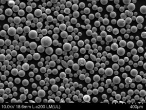
2) What particle size and shape are ideal for MIM feedstock?
- Typically D50 ≈ 5–20 μm with near-spherical morphology for high loading (58–64 vol%) and uniform debind/sinter. Very fine powders increase oxidation risk; proper passivation and low O/N are critical.
3) How do debinding routes differ (solvent vs catalytic vs thermal)?
- Solvent debinding removes soluble binder at 30–60°C; catalytic debinding (e.g., acetal in nitric acid atmosphere) is fast and uniform; thermal debinding pyrolyzes residual binder in controlled atmospheres. Choice depends on part size, geometry, and binder system.
4) What tolerances and densities are typical for MIM parts?
- As-sintered tolerances of ±0.3–0.5% of dimension are common, with 96–99.5% of theoretical density depending on alloy and cycle. Secondary sizing/CNC can tighten to ±0.1% where needed.
5) How does the MIM process compare to metal AM for small complex parts?
- For volumes above a few thousand pieces/year with small-to-medium part size and repeat geometry, MIM typically wins on cost per piece and throughput. AM excels for low-volume, highly customized designs or internal channels not feasible in MIM.
2025 Industry Trends: MIM Process
- High-load binder systems: New rheology modifiers enable 62–64 vol% powder loading for lower shrinkage variability and improved surface finish.
- Data-driven sintering: AI-assisted cycle control and in-situ O2 monitoring reduce distortion and lot-to-lot variability.
- Hybrid routes: Binder jetting “MIM-like” debind/sinter lines share furnaces and QA, enabling flexible capacity between MIM and BJ.
- Sustainability: Solvent recovery units and catalytic debinders cut VOC emissions; life-cycle data now included in RFQs.
- Medical/aerospace growth: More 316L, CoCr, and 17-4PH MIM parts qualified with biocompatibility and NADCAP-like furnace controls.
2025 KPI and Cost Snapshot (indicative ranges)
| メートル | 2023 Typical | 2025 Typical | Notes/Sources |
|---|---|---|---|
| Powder loading (vol%) | 58–62 | 62–64 | Higher loading reduces shrink and cycle time |
| As-sintered density (316L) | 97–98.5% | 98–99.5% | Atmosphere and cycle optimization |
| Dimensional Cp/Cpk (critical dims) | 1.0–1.3 | 1.33–1.67 | Statistical process control + AI tuning |
| Scrap rate (new launches, first 3 mos) | 6–10% | 3–6% | Better simulation and DOE |
| Solvent recovery efficiency | 70-85% | 85–95% | Closed-loop systems |
| Cost/pc vs CNC (5k–50k units) | −25–50% | −30–60% | Geometry and alloy dependent |
References: MPIF standards (e.g., MPIF 35), ASTM F2885/F3056/F3184/F3301 (related AM/MIM data practices), industry OEM notes, peer-reviewed MIM process studies
Latest Research Cases
Case Study 1: AI-Optimized Sintering of 17-4PH Gears (2025)
Background: An automotive tier-1 struggled with distortion and variable hardness on compact MIM gears at scale-up.
Solution: Implemented AI-assisted furnace control using thermocouple arrays and O2 ppm feedback; switched to higher-solids binder and added pre-sinter sizing fixture.
Results: Roundness out-of-tolerance reduced 58%; density increased from 97.8% to 98.9%; HRC uniformity ±0.8 vs ±1.7; scrap −41%; throughput +12%.
Case Study 2: Medical-Grade 316L MIM Endoscopic Jaws (2024)
Background: A medical OEM required high corrosion resistance and fine serration fidelity on micro components.
Solution: Gas-atomized 316L (D50 ≈ 12 μm, O ≤ 0.05 wt%); catalytic debind to minimize crack initiation; vacuum sinter with N2 backfill; final passivation per ASTM A967 and electropolish.
Results: As-sintered density 99.2%; Ra after electropolish 0.35–0.6 μm; passed ISO 10993 biocompatibility and ASTM F1089 corrosion tests; yield +9% vs prior thermal-debind route.
Expert Opinions
- Randall M. German, Professor Emeritus and MIM pioneer
Key viewpoint: “Elevated powder loadings and controlled atmospheres are closing the gap between MIM and wrought properties while stabilizing shrinkage for tighter tolerances.” - Dr. John Slotwinski, Materials Research Engineer, NIST
Key viewpoint: “Standardized data reporting and digital traceability from powder PSD/O/N to furnace logs accelerate cross-site MIM qualifications.” https://www.nist.gov/ - Dr. Anushree Chatterjee, Director, ASTM International AM Center of Excellence
Key viewpoint: “Harmonized COAs and furnace validation protocols, akin to NADCAP practices, are enabling regulated adoption of the MIM process in medical and aero devices.” https://amcoe.astm.org/
Practical Tools/Resources
- MPIF Standards (e.g., MPIF 35): MIM material and property specifications
https://www.mpif.org/ - ASTM standards relevant to MIM and sintering data/reporting (F2885, F3056, F3301)
https://www.astm.org/ - NIST: Measurement science for powder metallurgy and MIM process control
https://www.nist.gov/ - Senvol Database: Materials/equipment data helpful for benchmarking MIM vs AM routes
https://senvol.com/database - CFD/FEA simulation tools for feedstock and sintering distortion (e.g., Autodesk Moldflow, Simufact Additive/Sinter)
- HSE ATEX/DSEAR: Safe handling of fine metal powders during feedstock prep and debinding
https://www.hse.gov.uk/fireandexplosion/atex.htm
Last updated: 2025-08-27
Changelog: Added five focused FAQs, a 2025 KPI/cost table, two recent MIM case studies (AI-optimized sintering; medical-grade 316L jaws), expert viewpoints, and curated standards/resources for the MIM process.
Next review date & triggers: 2026-03-31 or earlier if MPIF/ASTM standards update, major OEMs publish new MIM property datasets, or significant advances in high-solids binder systems are released.